
Page 8 - Combined_134_OCR
P. 8
FLYING CARS
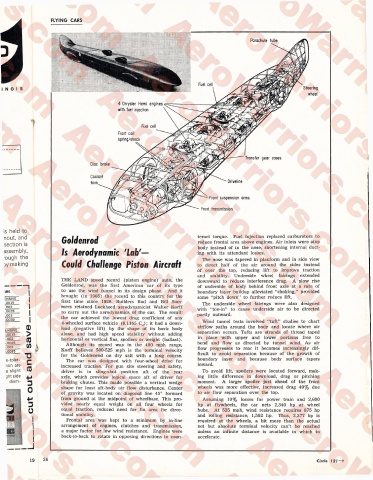
Parachute tube
Steering
4 Chrysler Hemi engines
with fuel injection
Fuel cell
Front coil
spring/shock
Transfer gear cases
Disc broke
Coolant
r Driveline
tank
Front suspension arms
Front transmission
Goldenrod teract torque. Fuel injection replaced carburetors to
reduce frontal area above engines. Air inlets were atop
body instead of in the nose, shortening internal duct
Is Aerodynamic 'Lab'— ing with its attendant losses.
The nose was tapered in planform and in side view
Could Challenge Piston Aircraft to direct half of the air around the sides instead
of over the top, reducing lift to improve traction
and stability. Underside wheel fairings extended
THE LAND speed record (piston engine) auto, the downward to reduce interference drag. A slow rise
Goldenrod, was the first American car of its type of underside of body behind front axle at a rate of
to use the wind tunnel in its design phase. And it boundary layer buildup alleviated “choking,” provided
brought (in 1965) the record to this country for the some “pitch down” to further reduce lift.
first time since 1928. Builders Bud and Bill Sum The underside wheel fairings were also designed
mers retained Lockheed aerodynamicist Walter Korff with “toe-in” to cause underside air to be directed
to carry out the aerodynamics of the car. The result: partly outward.
the car achieved the lowest drag coefficient of any
4-wheeled surface vehicle (0.1165 Cd); it had a down Wind tunnel tests involved “tuft” studies to chart
load (negative lift) by the shape of its basic body airflow paths around the body and locate where air
alone, and had high speed stability without adding separation occurs. Tufts are strands of thread taped
horizontal or vertical fins, spoilers or weight (ballast). in place with upper and lower portions free to
Although its record was in the 400 mph range, bend and flow as directed by tunnel wind. As air
Korff believes 500-525 mph is the terminal velocity flow progresses to rear it becomes increasingly dif
for the Goldenrod on dry salt with a long course. ficult to avoid separation because of the growth of
The car was designed with four-wheel drive for boundary layer and because body surface tapers
increased traction. For gun site steering and safety, inward.
driver is in sling-shot position aft of the rear To' avoid lift, spoilers were located forward, mak
axle, which provides logical space aft of driver for ing little difference in download, drag or pitching
braking chutes. This made possible a vertical wedge moment. A larger spoiler just ahead of the front
shape for least aft-body air flow disturbance. Center wheels was more effective, increased drag 49% due
of gravity was located on diagonal line 45° forward to air flow separation over the top.
from ground at the midpoint of wheelbase. This pro Assuming 10% losses for power train and 2,600
vided nearly equal weight on all four wheels for hp at flywheels, the car nets 2,340 hp at wheel
equal traction, reduced need for fin area for direc hubs. At 525 mph, wind resistance requires 875 hp
tional stability. and rolling resistance, 1,502 hp. Thus, 2,377 hp is
Frontal area was kept to a minimum by in-line required at the wheels, a bit more than the actual
arrangement of engines, clutches and transmission, net but absolute terminal velocity can’t be reached
a major factor for low wind resistance. Engines were unless an infinite distance is available in which to
back-to-back to rotate in opposing directions to coun accelerate.
Circle