
Page 3 - Combined_39_OCR
P. 3
W. P. Wright 3 February 18, 1970
W = 160
Centrifugal Weight Total
Force (lbs) (lbs) (lbs)
Vertical 188.2 134.2 322.4
Lateral 289.8 - 87.1 202.7
This wide variation in load between drivers and for the same driver between
straightaway and turns establishes a requirement for more than one spring rate and
a preloading mechanism to restrain the seat during periods of low loading due to
centrifugal forces.
To upgrade the load carrying capability of this Viking torsion bar seat, torsion
bars to handle the additional load were sized based on the dimensions of the torsion
bars in the seat (.188” x 1.25”) and its stated capabilities. These torsion bars are
being constructed in two sizes, . C 7 1 X 1.2 and .22” x 1.25”, to accommodate
various weight drivers. Three sets of torsion bars provide six possible spring rates
(k) to satisfy the equation / k/M . Loading of the seat can be accomplished
via a chain which would restrain the seat during periods of low centrifugal force pro
viding a condition similar to the present rigid attachment except for the shock absorber
which will introduce damping and so limit the response. During periods of high cen
trifugal loading, the chain would relax allowing the isolating mechanism to function.
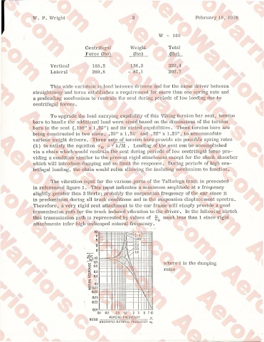
The vibration input for the various parts of the Talladega track is presented
in referenced figure 1. This input indicates a maximum amplitude at a frequency
slightly greater than 3 Hertz; probably the suspension frequency of the car since it
is predominant during all track conditions and in the suspension displacement spectra.
Therefore, a very rigid seat attachment to the car frame will simply provide a good
transmission path for the track induced vibration to the driver. In the following sketch
this transmission path is represented by values of much less than 1 since rigid
attachments infer high undamped natural frequency.
u
pry I ro/ •° P i O cn -s where 6 is the damping
RESPONSE 0.3 ratio
0.2
MOTION 0.07
o.i
0.05
0.03
1 \1
0.02
1
o o
o 0.2 0.5 1.0 2 3 5 7 10
FORCING FREQUENCY w
UNDAMPED NATURAL FREQUENCY