
Page 2 - Combined_140_OCR
P. 2
LAYOUT the full-size tunnel could be thoroughly examined before
construction.
In order to fulfill the overall purpose, the size of the The pilot tunnel was accu irtant
tunnel’s working section was fixed so that full-scale vehicles >, such as the air duct, i •-
and models could be tested without choking or diverting tion, collector, and fail, were, concerned and ........
the airflow to ail unacceptable degree. With a blockage obtained provided valuable data for dcMiled ■ .;n of the
raiio of 3% (maximum 10%) based on the. projection of the full-size luiitic.l. When operating, the full-scale sisncl : .r
»> tile lirst lime., Il was found ih.u
model considered generally permissible, an area of 37.5 m
juticipated m any project had been ''
('H) ’i ::q 11) was laid down for the cross-section of the air-
ol tests carded out with the pilot ijuiuel. Iho lev/ rmi.ii.il-
sirdam o! the wind tunnel with a working section length
ing prob let i is. were, remedied quickly with design d-in d —
of 10in ft).
vices.
The. tunnel was constructed according to the well-known
The pilot wind tunnel was ins tailed in a soundproof room
Gouingcr design which employs a horizontal return duct.
in the building erected for the jargc-scalc. tjuuicl <• th.it
This type of construction requires only a relatively small
it can be used for future calibrations of all types of • :
power consumption as part of the airstream energy is re
pr<>bcs for pressure, spec.1, direct and ’
covered through this duct. The power consumption of the
a large number of nonproductive calibrations need not be
wind tunnel fan of 2600 kW (3480 hp) was determined from
made with the climatic wind tunnel itself.
flic size of the cross-section of the airstream and the required
maximum speed of 150 km/h (93 mph).
ASSEMBLY ANU EJECTION
Force and pressure measurements are the basic items
in ilie aerodynamic testing programs and a mechanical self-
Dingier AG of Zweibrucken was appointed general con
compeiisatiug six -component balance is provided for meas
tractor for the ^instruction of the climatic wind tunnel in
uring aerodynamic forces and moments. This unit can be
the. autumn of .Unlm l.'he order covered supply and .e. cinbiy
related with the. test vehicle in an infinitely variable, man
of the complete iu:.t.i Iimi but. did not (n< hide rivcfioii
ner lor the. simtilaiion of airflow direction. A system ol
and civil engineering operations for which ;m-'ih -r firm was
electrical sensors with automatic high-speed step motors
commissioned direct ly byilie Volksw.i ’ ii <b>. The tunno:
is used for measuring complete pressure distributions in very
site, was prepared in the i.iiiniiierol ’Im and r.oepmai mil > 2 the
short time.
main contractor and the firm employ d lor the. election
In the majority of cases, the functional tests require the
and civil m inccri
exact reproduction of engine output. Accordingly, simul
wind tunnel formally opened in December 1963.
taneous control is provided for the air temperature of -30 C
(-22 F) to +50 C (122 F) and for ambient relative humidity
(up to 25% KI I tit +50 C) especially at high temperatures.
The Jan output which is converted into frictional heat is
removed by a high-capacity air cooler with an active heat
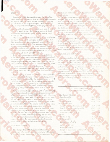
Table 1 - Main Dimensions, VW
2
exchanging surface of approximately 5000 m (53.S20 sqft). Climatic Wind Tunnel •
Power consumption of the compressor-driven evaporator
refrigerating system is about 2800 kW (3760 hp) . o work- Wind Tunnel Buildi
ing section can be closed with a movable steel cover watch, Length, m (ft) 82.0 (269)
like the complete return duct, is thermally insulated to Width, m (ft) 49.0 (161)
avoid the exchange of heat with the surrounding air as well I leight, in (ft) 21.0 (69)
as the formation of ice. 'Hie engine output itself is tested Wind 'Funnel Duct
by braking on a programmed dynamometer test bench. Le.ngm of longimdinal ;ixis, in (ft) 52.0 (171)
Ln order to obtain optimum utilization from tills rela- Length of transverse, axi s. in (ft) 20.0 (66)
lively. - ompn e "size installation, an IBM 1710/1620 Maximum diameter, m (1!) 13,8 GO
'•ompnte.r has been instailed for process control and rnonitor- Minimum diameter, m GO 8.0. (16)
mqo: the wind tunnel. Besides controlling the test units and Nozzle
: wo r kin narametcrs such as speed, temperature, and Width, m (ft) 7.5 (•■’)
.. nbient humidity, the computer automatically records, Height, m (ft) 5.0 (-6)
stores, converts, prints, and plots the test values.
Intake area, in” (ft ) (1614)
. 2 2
PILOT WIND TUNNEL Exit area, m (ft ) 37.5 (40')
Contraction ratio
After design of the VW climatic wind tunnel had been Length of free-stream working section.
completed, a pilot tunnel was constructed at a 1:15 scale, Ill (ft) 10.0 ( )
*o that the dynamic phenomena in the free airstream of