
Page 3 - Combined_140_OCR
P. 3
MAIN DIMENSIONS the rated speeds are reduced to the fan speeds through a two
stage reduction gear. A pole changeable motor was chosen
TiaJImain dimensions of the wind tunnel building and so that sensitive air speed control can be maintained even
... in Ik’. 1, at the lowest wind spc ds.
..o work? The fan has a number oi interesting design details. The
but the complete rcturiJduct as well, so that the size of rotor is overhung mounted in spite of its large dimensions
Q
me cnclomd volume amounts to approximately 75,000 and the main bearing is located in a rotationally symmetri
cal supporting member borne by seven shaped vanes. A
,uno,600 cu it).
. L) f< >llows the fan hub in o . ■ * tlx unit.
It is held on the fan end oy straightener vanes which consist
SPbwit'lOA 1IONS
of 19 nonprofiled sheet metal blades; three further shaped
supports follow downstream.
essential details ol tile specifications relating to the main Hydraulic control of the 10-fan vanes is synchronized.
o
*
ems r . . ctimalic win . th . ’ . o A flat-topped piston axially fixed and rotating with the hub
Ao.: sy/.cm, ae.mdyxamic balance, dynamometer test bench, divides a hydraulic cylinder with axial displacement into
and computer, arc given in Table 2 and operation of the two oil pressure chambers. Grooves are provided for each
a d< ... ing sec- vane on the outside of the hydraulic cylinder, in which are
Q
run the slide rings of the adjusting cranks, if the control
l?.j Am of the wind tunnel consists oi a single - pressure is altered on one side of the piston, the hydraulic
Xia 1 compressor with 10 vanes and has a diameter cylinder is displaced in the longitudinal direction and ad-
•j
'/S
co
01 Tae rated speed is 175 rpm or llu rpm as justs the pitch angle through the cranks which arc welded
rccuircd. Air speed is controlled by infinitely variable ad to the blade beams. Oil is fed to the two cylinder chambers
justment of the pitch angle of the blades. through ring-shaped chamber . A driliings in the connecting
A pole changeable c-phase asyncWonous motor with rod. Operating pressure has purposely been limited to ap
raws meeds of cither 1489 rpm or 994 rpm is used to drive proximately 10 afu (156.2 psia) so as to obtain the maxi
the km. The operating voltage of the motor is 6000 V and mum life from the parts subject to wear.
in
G O
4
4S000
<r 1 1
•(-----
lux-U
co
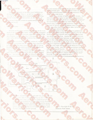
Cl) le, (■’.) working wri i.ou, (•’>) collector, (4) movable test
. - n s ■ )V r, (5) electric motor with gear, (6) l.m, (7) Jif"
li iK
(5) corner v.mm (9) air cooler, (1.0) honeycomb flow
mlgmoner. (Li) turbulence st’fcCiis. (12) settling chamber,
(:.. ) acrodyn.imw: balance, (14) program-controlled dynam-
o:ir cm csi bench, (15) control center, (16) process control
.7 . .a, (17) c.ecLomuchanical workshop, (18) office, (19) Fig. 1 - Plan view of the VW
m.:<umic room (refrigeration system) Climatic Wind Tunnel