
Page 6 - Combined_41_OCR
P. 6
wheels, for instance. But this com
pensation is not completely satisfac
tory.
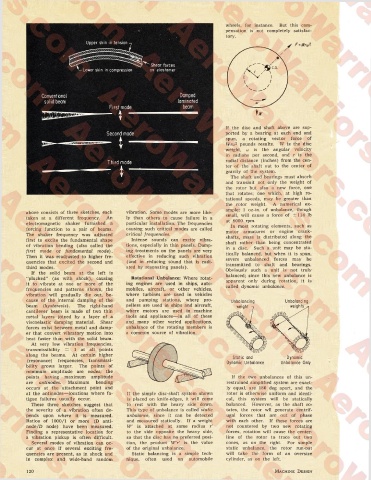
Upper skin in tension
r -Wrw2-
\
\
’ Shear forces
Lower skin in compression on elastomer
Conventional Damped
solid beam laminated
beam
If the disc and shaft above are sup
Second mode ported by a bearing at each end and
spun, a rotating vector force of
Wroj2 pounds results. W is the disc
weight, (j is the angular velocity
in radians per second, and r is the
Third mode radial distance (inches) from the cen
ter of the shaft out to the center of
gravity of the system.
The shaft and bearings must absorb
and transmit not only the weight of
the rotor but also a new force, one
that rotates; one which, at high ro
tational speeds, may be greater than
the rotor weight. A numerical ex
ample: 1 oz-in. of unbalance, though
above consists of three sketches, each vibration. Some modes are more like
taken at a different frequency. An ly than others to cause failure in a small, will cause a force of ±114 lb
electromagnetic shaker furnished a particular installation. The frequencies at 8000 rpm.
In most rotating elements, such as
forcing function to a pair of beams. causing such critical modes are called motor armatures or engine crank
The shaker frequency was adjusted critical frequencies. shafts, mass is distributed along the
first to excite the fundamental shape Intense sounds can excite vibra shaft rather than being concentrated
of vibration bending (also called the tions, especially in thin panels. Damp in a disc. Such a unit may be sta
first mode or fundamental mode). ing treatments on the panels are very tically balanced, but when it is spun,
Then it was readjusted to higher fre effective in reducing such vibration
quencies that excited the second and (and in reducing sound that is radi severe unbalanced forces may be
transmitted to shaft and bearings.
third modes. ated by resonating panels).
If the solid beam at the left is Obviously such a unit is not truly
“plucked” (as with shock), causing Rotational Unbalance: Where rotat balanced; since this new unbalance is
apparent only during rotation, it is
it to vibrate at one or more of the ing engines are used in ships, auto called dynamic unbalance.
frequencies and patterns shown, the mobiles, aircraft, or other vehicles,
vibration will gradually die out, be where turbines are used in vehicles
cause of the internal damping of the and pumping stations, where pro Unbalancing Unbalancing
beam (hysteresis). The right-hand pellers are used in ships and aircraft,
cantilever beam is made of two thin where motors are used in machine
metal layers joined by a layer of a tools and appliances—in all of these
viscoelastic damping material. Shear and many other varied applications,
forces exist between metal and damp unbalance of the rotating members is
er that convert vibratory motion into a common source of vibration.
heat faster than with the solid beam.
At very low vibration frequencies,
transmissibility = 1 at all points
along the beams. At certain higher Static and Dynamic
(resonance) frequencies, transmissi
Dynamic Unbalance Unbalance Only
bility grows larger. The points of
minimum amplitude are nodes; the
points having maximum amplitude If the two unbalances of this un
are antinodes. Maximum bending restrained simplified system are exact
occurs at the attachment point and ly equal, are 180 deg apart, and the
at the antinodes—locations where fa If the simple disc-shaft system shown rotor is otherwise uniform and identi
tigue failures usually occur. is placed on knife-edges, it will come cal, this system will be statically
These three sketches suggest that to rest with the heavy side down. balanced. However, as the shaft ro
the severity of a vibration often de This type of unbalance is called static tates, the rotor wll generate centrif
pends upon where it is measured. unbalance, since it can be detected ugal forces that are out of phase
Ratios of 1000/1 or more (D anti- and measured statically. If a weight with each other. If these forces are
node/D node) have been measured. W' is attached at some radius r' not countered by two new rotating
Finding a representative location for to the side opposite the heavy side, forces, rotation will cause the center-
a vibration pickup is often difficult. so that the disc has no preferred posi line of the rotor to trace out two
Several modes of vibration can oc tion, the product W'r' is the value cones, as on the right. For simple
cur at once if several exciting fre of the original unbalance. static unbalance, the rotor run-out
quencies are present, as in shock and Static balancing is a simple tech will take the form of an oversize
in complex and wide-band random nique, often used on automobile cylinder, as on the left.
120 Machine Design