
Page 7 - Combined_41_OCR
P. 7
VIBRATION TESTING
simplest means of sensing and measuring accelera
tion. Such a system consists of strain gages ce
mented to the top and bottom surfaces of a beam
and connected electrically to a simple meter, Fig. 2. Tension
gages (4)
Acceleration of the base up and down changes Motion
the resistance of the gages, which is reflected pro
portionally on the meter.
For very low frequencies—up to about 0.5 Hz—
the d-c-sensing meter of Fig. 2 could be used. The
pointer would be centered for zero acceleration. It
would swing left for upward acceleration and right
for downward acceleration. But if the vibration
frequency were increased beyond this range, the
pointer could not follow the signal but would
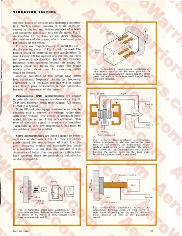
merely quiver about zero. An a-c-sensing meter Fig. 3—Simplified piezoresistive accelerometer.
This sensor operates on the same principle as
would be needed. a strain-gage accelerometer, except that the strain
Another limitation of this simple SGA stems gages are replaced with four small bits of semi
from its natural frequency. As the test frequency conductor material.
approaches fN of the SGA, readings will be higher
even though peak acceleration is held constant—
because of resonance of the sensor.
Piezoresistive (PR) accelerometers are similar
in principle to strain-gage accelerometers, Fig. 3.
—o
They are, however, much more rugged; full output
Signal out
at 2500 g is typical. ——o
Some PR and strain-gage accelerometers can be
operated with a “carrier” a-c voltage, rather than
with a d-c voltage. The carrier is amplitude-mod
ulated by the action of the accelerometer. This
type of electrical signal is more easily amplified —o
(especially at very low frequencies), but must be Power in
—o
demodulated prior to readout.
I IVRUp
Servo accelerometers are force-balance or force- Force-rebalance coil
rebalance accelerometers, Fig. 4. They are partic Fig. 4—Servo (force-rebalance) accelerometer.
ularly suited for measurement of very low (to When acceleration of the case moves the mass
from its rest position, the displacement pickup
zero) frequency motion and extremely low levels sends a signal to the servo amplifier. The ampli
of acceleration—to less than one millionth of a g. fier current (to the force-rebalance coil) exactly
Accuracies of better than one part per million have balances the inertial force on the mass while
been achieved; these are particularly valuable for furnishing a proportional output signal.
inertial navigation.
Piezoelectric crystal bar
Battery
Motion
Gage /r^
Motion Gage R2 pi 0
D“C
voltmeter ---------o
’’-"Base t Signal out
--------o
Vibrating
structure Test structure
Fig. 5—Simplified piezoelectric (crystal) ac
Fig. 2—Simplified strain-gage accelerometer. Ac celerometer. Bending, shear, or compressive in
celeration on base deflects cantilevered beam due ertia forces—depending on the specific accelero
to inertia of W, which, in turn, changes strain meter—generate an emf in the piezoelectric
gage resistances Ri and R2. crystal.
May 29, 1969 121