
Page 6 - Combined_31_OCR
P. 6
CAUTION — Release air pressure, by pulling out button on valve, before performing any service.
Air Suspension
A System
1. Disconnect truck air supply and remove seat from
truck.
2. Wedge upper seat in top position by using wood
shim under tube located beneath front of seat
cushion or by shim under tube located below back
cushion.
co Disengage seat cushion from assembly by removing
nuts, lockwashers and washers (index Nos. 48, 47
and 46). Move seat cushion forward to free nylon
rollers (index 45) from housing under seat cushion.
Release air spring assembly by removing machine
TF
screw (index No. 41) from base of air bag.
Disengage air reservoir from side panels, by remov
IO
ing cap screws and lock washers (index Nos. 27
and 12).
This permits entire air suspension system to be re
moved as a unit.
Air Spring Assembly
(index IMo. 33)
Remove retainer clip D, permitting hose assembly
tH
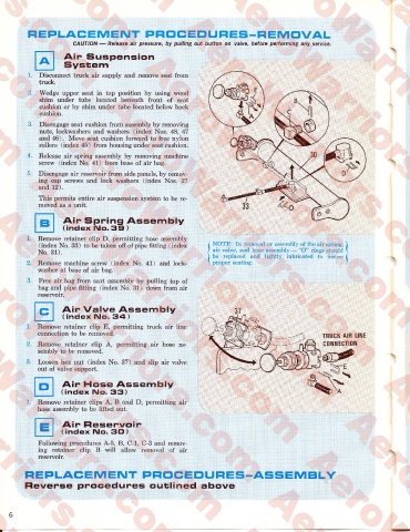
(index No. 33) to be taken off of pipe fitting (index NOTE: In removal or assembly of the air spring, 1
No. 31). air valve, and hose assembly — “O” rings should k
be replaced and lightly lubricated to insure 1
Remove machine screw (index No. 41) and lock proper seating. /
washer at base of air bag.
Free air bag from seat assembly by pulling top of
bag and pipe fitting (index No. 31) down from air
reservoir.
c Air Valve Assembly
(index IMo. 34)
Remove retainer clip E, permitting truck air line
connection to be removed.
TRUCK AIR LIME
to Remove retainer clip A, permitting air hose as CONNECTION
sembly to be removed.
co Loosen hex nut (index No. 37) and slip air valve
out of valve support.
□ Air Hase Assembly
(index IMo. 33)
1. Remove retainer clips A, B and D, permitting air
hose assembly to be lifted out.
Air Reservoir
(index IMo. 30)
Following procedures A-5, B, C-l, C-3 and remov
ing retainer clip B will allow removal of air
reservoir.
REPLACEMENT PROCEDURES-ASSEMBLY
Reverse procedures outlined above
6