
Page 7 - Combined_31_OCR
P. 7
Standard Shock
Absorber
u REMOVAL
1. Wedge upper seat in top position following
removal procedure A-l.
2. Release air pressure from air bag by pulling
out button (index No. 38) on air valve.
I 4. removal procedure A-4.
Remove seat cushion only following
3.
Wire side panel assemblies (index Nos.
28 and 29) across front of seat to retain
their position. !0J
5. Remove (2) snap rings (index No. 10)
from ends of hinge shaft (index No. 18)
Replace (2) roll pins (index No. 20)
at front of shock absorber. oi
Remove hinge shaft (index No. 18) in hinge shaft, locking roll pin on right hand
by tapping out from left hand to right hand side in nibs in bent-up ear.
side. This operation frees (2) washers co Replace hinge shaft (index No. 18)
(index No. 15). at front of shock absorber, driving shaft from
right hand to left hand side. Serrated end
7. Remove (2) roll pins (index No. 20)
from hinge shaft at rear of shock absorber. of shaft to enter shock lever (index No. 17)
Use small Dia. punch. last. Drive shaft through (2) washers (index
X Remove hinge shaft (index No. 19) at rear No. 15) and through shock absorber loop.
of shock absorber. This frees shock absorber. Replace (2) snap rings (index No. 10)
at ends of front hinge shaft (index No. 18).
Line up side panels right hand and
U 0
left hand retaining the 20.00 dimension over
side panels.
ASSEMBLY co Reassemble seat cushion following
assembly procedure A-4.
1. With shock absorber (index No. 22) Inflate air spring assembly by pushing in
in proper position, replace hinge shaft button (index No. 38) on air valve.
(index No. 19) at rear of shock. 00 Remove shims.
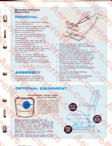
OPTIONAL EQUIPMENT
INTERCHANGEABLE CUSHION COVERS.
Feature on all Viking Seats
If either cover is damaged and
requires replacement, the opera
tion is simple. Remove cushion
from seat frame. The vinyl cover
is held in place by fastener clips. E
By opening the clips the cover
is removed quickly and easily.
I A new foam cushion and fastener
clips are included with each
cover assembly.
Optional Equipment (available at extra cost)
EXTRA DUTY SHOCK ABSORBER — For exceptionally
severe operating conditions — off highway or over
rough terrain — gravel or dump truck, concrete mixers,
earth moving or similar equipment. This option can
be used if seat to floor clearance is 2%" or more.
See your dealer for further information. [iIH
ARM REST — Easily attached to side panel assembly.
Folds up out of the way when not in use.
SAFETY BELT KITS—Can be easily installed as shown
in illustration. 30847-801 Lap Kit; 30848-801 Floor Kit.